Description
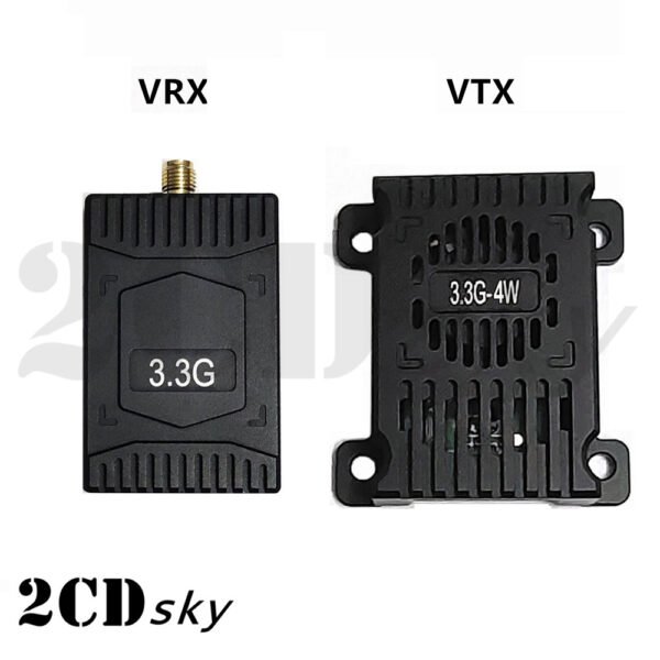
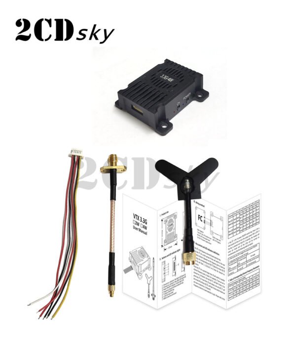
VTX Manual
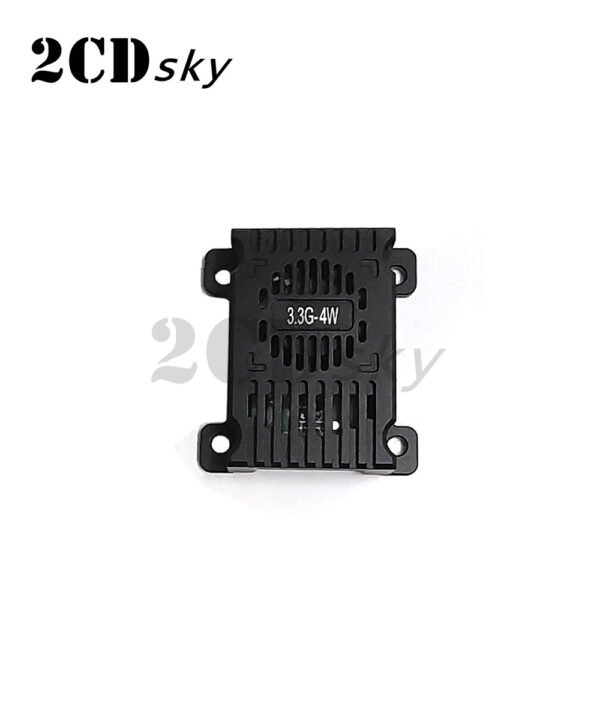
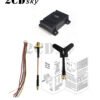
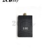
1. Product size
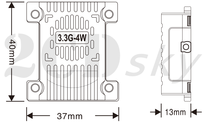
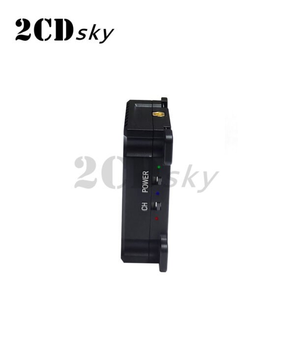
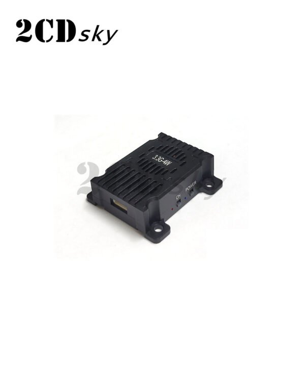
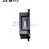
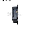
2. Buttons and LED indicator lights

① Channel no.indicator: Red light LED (band A)
②Channel no.indicator: Blue light LED (band B)
③Power ON/OFF indicator: Green light LED
④Frequency channel & band selection key
⑤Tx Power ON/OFF key
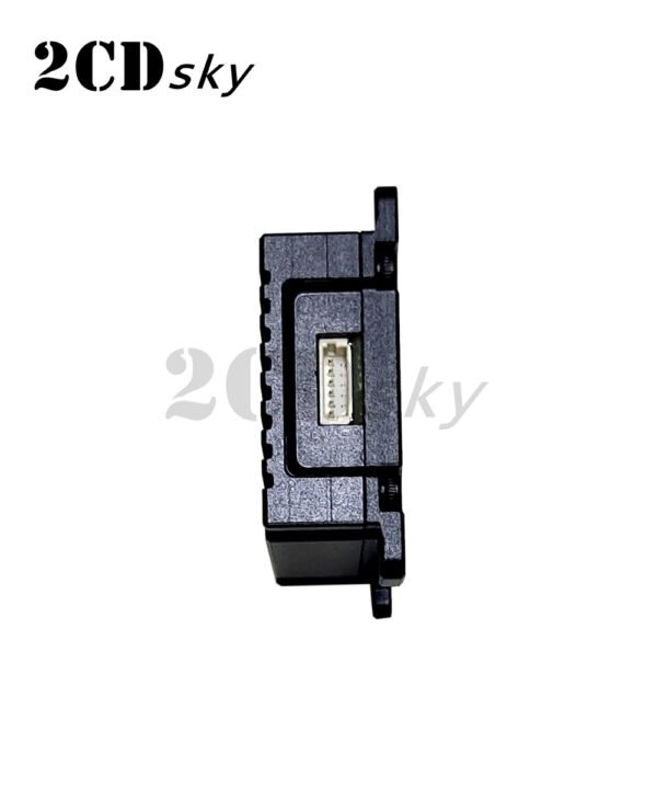
⑥1.0 6P wiring socket
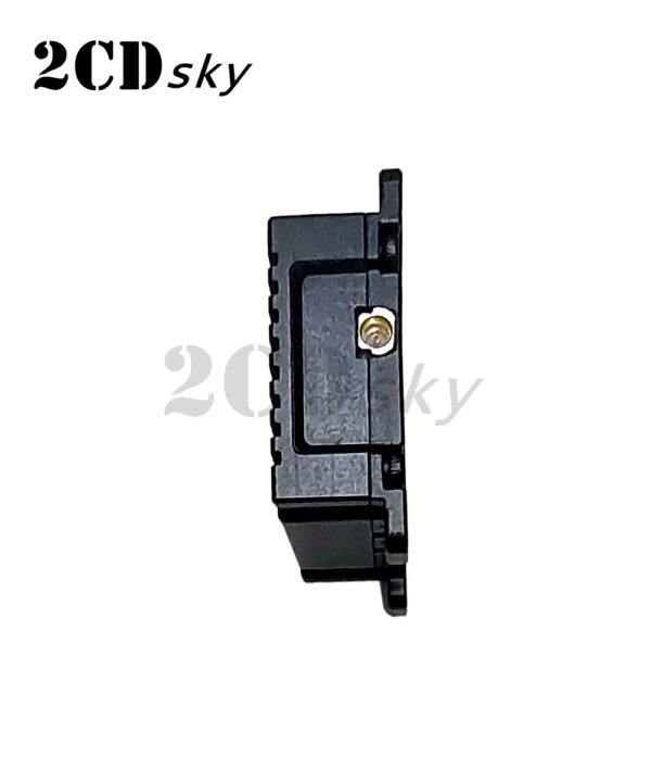
⑦MMCX antenna connector
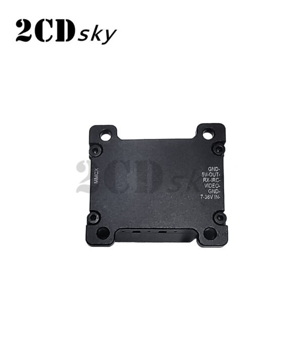
3. Wiring method
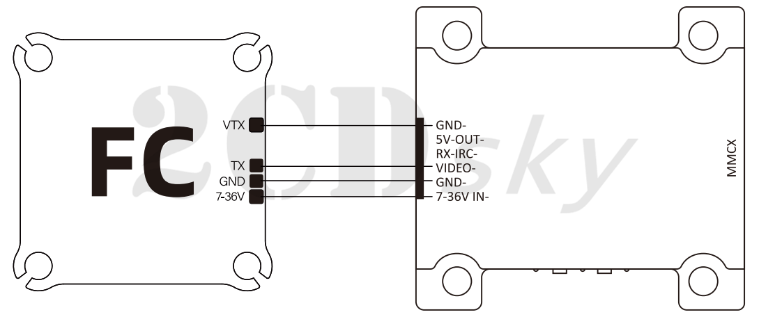
GND: Negative VIDEO: lmage input
7-36V IN: 2-8s, VTX positive input GND: VTX negative
RX-IRC: IRC Tramp signal input
5V-0UT: 5V power supply output
4. Key control and LED indicators definition:
1. Key ④ is the frequency channel & band selection key. Press key ④ for a short period of time will switch to the next frequency channel. Depends on the frequency plan or band we are using, the corresponding red LED ①(band A) or blue LED ②(band B) will flash 1,2,3,4,5,6,7 or 8 times for channe!no. indication.
Press key ④ for a period longer than 3S will switch to another channel frequency plan or band. For example, if now we are in channel no.3 of band A,the red LED will flash 3 times. lf we press key ④ for more than 3S and release, the red LED will be turned off and blue LED ② will flash 3 times which means we are now in channel no. 3 of band B.
Frequency channel or band selection is cyclic. Please refer tothe following table for details:

2. Key ⑤ is the Tx power ON/OFF control key. Press it for a short period of time to turn the output power ON or OFF. lf the key is pressed and held for 3 seconds, the module will enter Pit mode and all the LEDs will be turned on simultaneously. See the following table for details:

5. Table of Corresponding Channel Frequency Parameters

VRX Manual
1. Product size
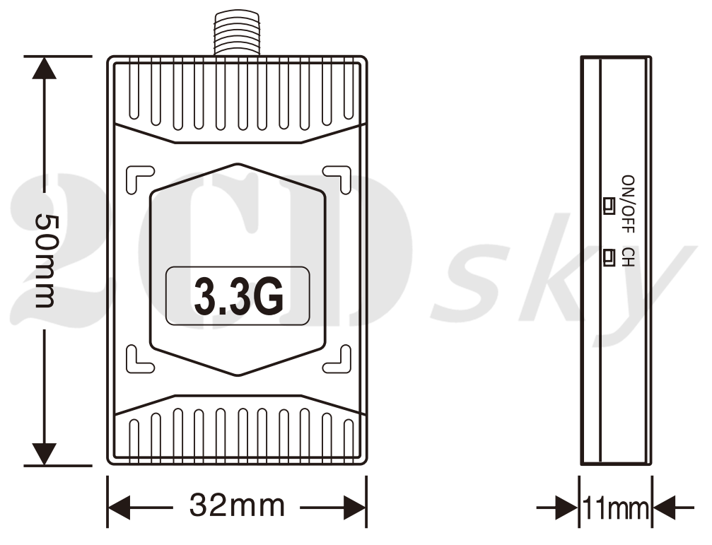
2. Buttons and LED indicator lights
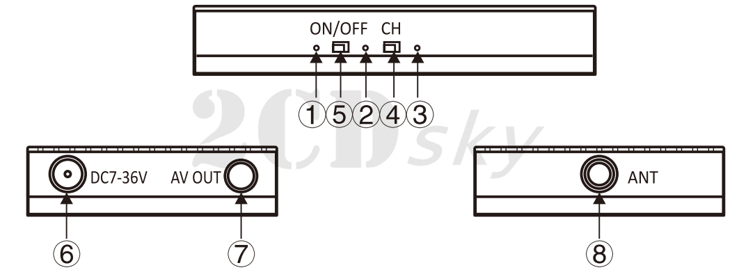
①Power ON/OFF indicator: Green light LED
②Channel no.indicator: Blue light LED (band B)
③Channel no.indicator: Red light LED (band A)
④Frequency channel & band selection key
⑤Power ON/OFF key
⑥DC jack
⑦Phone jack
⑧Antenna connector
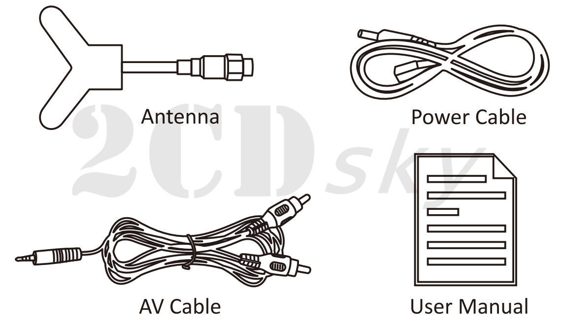
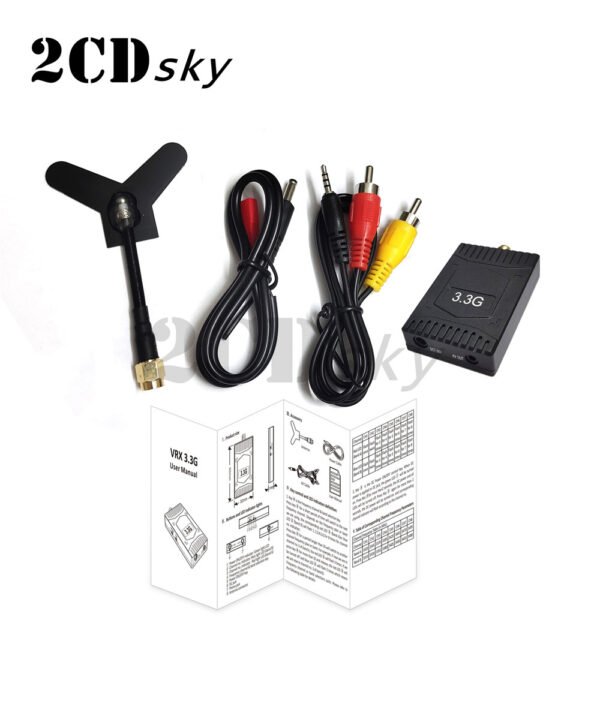
3. Accessory
4. Key control and LED indicators definition:
1. Key ④is the frequency channel & band selection key. Press key ④ for a short period of time will switch to the next frequency channel. Depends on the frequency plan or band we are using, the corresponding red LED ③(band A)or blue LED 2(band B) will flash 1,2,3,4,5,6,7 or 8 times for channel no.indication.
Press key ④ for a period longer than 3s will switch to another channel frequency plan or band. For example, if now we are in channel no. 3 of band A, the red LED 3 will flash 3 times. lf we press key 4 for more than 3S and release, the red LED ③ will be turned off and blue LED ② will flash 3 times which means we are now in channel no. 3 of band B.
Frequency channel or band selections cyclic. Please refer to the following table for details:
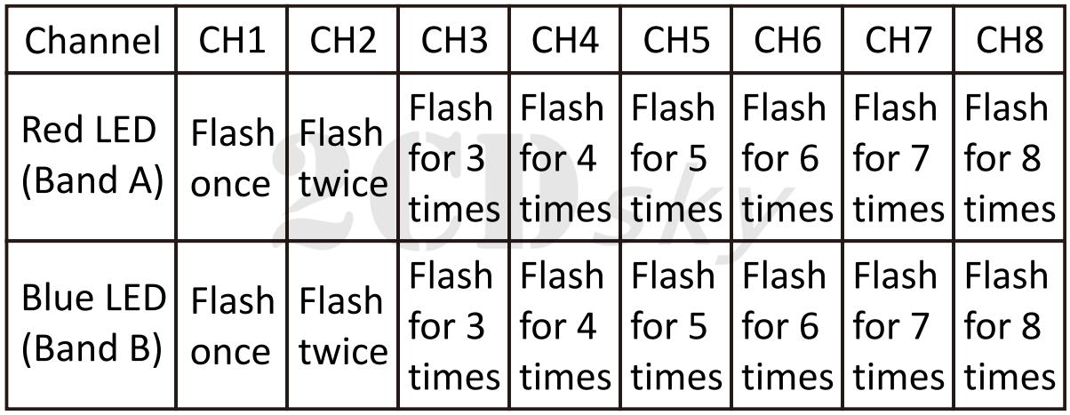
2.Key ⑤ is the DC Power ON/OFF control key. When DC power is applied to DC jack, the green LED ① will be turned on. Press Key ⑤ for more than 2 seconds, the DC power and all LEDs will be turned off. Press Key ⑤ again for more than 2 seconds, the DC power will be turned on, and corresponding channel indicator will flash according to the channel no.
5. Table of Corresponding Channel Frequency Parameters





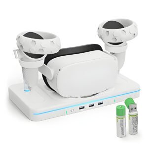 3VR glasses charger base handle storage stand Wireless RGB seven-color light
Reviews
There are no reviews yet.